The main types of antennas their history and application
What is an antenna?
An antenna is a device that converts electricity into radiated radio waves and vice versa, received electromagnetic waves into current.
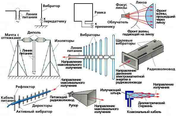
The antennas are extremely diverse, have a very different shape. The simplest antennas in the form of a stretched piece of wire, conductor systems, waveguides, they can have reflectors and lenses, can be completely different sizes. The latter, by the way, directly depends on the wavelength at which the antenna is designed to work, in order to effectively emit energy, its size should be close to the operating range, respectively, a large wavelength = a large antenna length. The operating frequency range at which the antenna operates efficiently is called the bandwidth.
The first devices with which, theoretically, it is possible to receive electromagnetic vibrations appeared in the middle of the eighteenth century. Although at first no one thought about using them in this way, this is an ordinary lightning rod, invented in 1751 by B. Franklin, because in fact a long, vertically positioned, grounded wire raised high above the surface can be called an antenna. In 1876 , Vol . Edison used a receiving antenna in his receiver of electromagnetic vibrations, in 1885 he had already proposed a method of wireless telegraphic communication using electromagnetic waves and received a patent for it. He managed to successfully conduct communications between ships and moving trains. His inventions were the beginning of the long-wave machine telegraph, which was used until the second half of the 1930s.
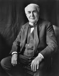
Thomas Alva Edison (1847 — 1931)
Initially, the transmitting elements were known as "terminals" or "terminals". The origin of the word "antenna" is attributed to Guglielmo Marconi, who during his experiments in 1895 used a pole with a wire attached to it, being an Italian researcher called a pole with a wire l'entenna, and after Marconi gained fame, the word spread first among other researchers, and later among the general public.
Nowadays, this term can refer to the entire structure, including the supporting structure, housing, etc.

Guglielmo Marconi (1874 — 1937)
The oscillating circuit and the first transmitting antennas
A large number of antennas are made in the form of an oscillatory circuit. An oscillatory circuit is a device, the simplest version of which consists of an inductor, a capacitor and an electric power source, which is an electrical circuit whose operation generates electromagnetic oscillations. It can be closed and open.
A closed circuit practically does not emit its vibrations into the surrounding space and creates a localized electromagnetic field mainly around the inductor.
If you push the plates of the capacitor apart, the intensity of the emission of electromagnetic waves into the surrounding space will increase, thus we will get an open oscillatory circuit, also called a vibrator, i.e. emitting (transmitting) the antenna.
The first transmitting antenna, without realizing it, was created in 1886 by the notorious Heinrich Hertz, during his experiments to prove the existence of electromagnetic waves.
Heinrich Rudolf Hertz (1857 — 1894)
The so-called symmetrical Hertz vibrator is a rectilinear electrical conductor (for example, a copper wire) with a small gap in the middle, fed at the break points by a high-frequency current generator. After Hertz's research, many physicists repeatedly repeated the experiment, reproducing the vibrator with some changes, so Augustino Rigi modified the device to get a shorter wavelength than Hertz's, but that's another story. We are also interested in the fact that this is essentially a dipole antenna — the simplest and extremely common non-directional vibrator antenna consisting of 2 identical conductors between which a signal is received.
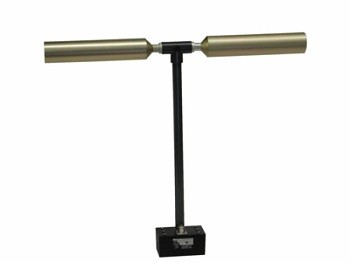
An example of a modern dipole antenna
If there are symmetrical vibrators, then there must be non-symmetrical vibrators, i.e. antennas that somehow do not have a plane of symmetry. Such really exist. They have a different shape or length of shoulders, a different number of conductors, this type includes J-shaped antennas.
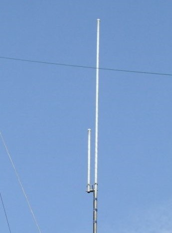
Example of a J-shaped antenna
Also, in some situations, the symmetry of the antenna arms is not necessary, for example, if the vibrator is located at a certain distance from the ideally conducting plane, then according to the principle of mirror images, it is equivalent to two vibrators at twice the distance. However, since such antennas are affected by the properties of the earth, they are usually grounded or counterbalanced to improve efficiency. Marconi, already mentioned above, invented such antennas, in 1896 he patented a monopole antenna.
A monopole antenna is the simplest class of antennas among asymmetric vibrators, consisting of a straight conductor in the form of a rod, usually installed perpendicular to the ground plane.
Antennas using radio wave reflection
Another particularly important invention of Hertz are parabolic reflectors (reflectors). Continuing his experiments, in 1887 he suggested that electromagnetic waves can be reflected from objects as well as light. With the help of a pair of galvanized steel reflectors with an aperture of 1.2 meters, he managed to achieve spark excitation of dipole antennas. With the help of such a design, Hertz demonstrated to the public the existence of electromagnetic waves.
The importance of the reflector is that it allows you to increase the gain. This characteristic means the ability of the antenna to concentrate the signal in a certain direction. It is measured in decibels (dB). It can also be described as the ratio of energy at the input and output of the antenna.
An example of using a reflector is the well-known television satellite dishes (dishes), which are widely used to organize communication between distant objects, for example in satellite television.
The "dish" itself is a reflector, it focuses the waves on the irradiator by reflection, which receives the focused signal. The reflector and the irradiator must have the same radiation pattern so that the antenna has the maximum gain, and the energy does not go idle.
In fact, the reflector does not have to be solid, it can be mesh, which firstly facilitates the overall weight, and secondly contributes to greater self-cleaning from rain and snow, thereby contributing to greater signal stability in adverse weather conditions.
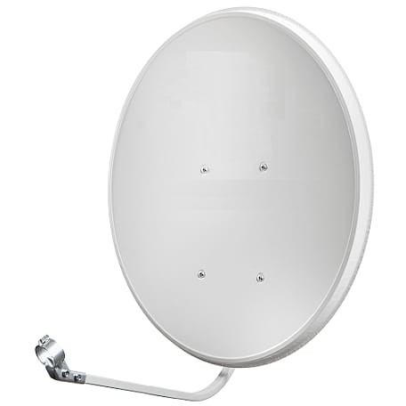
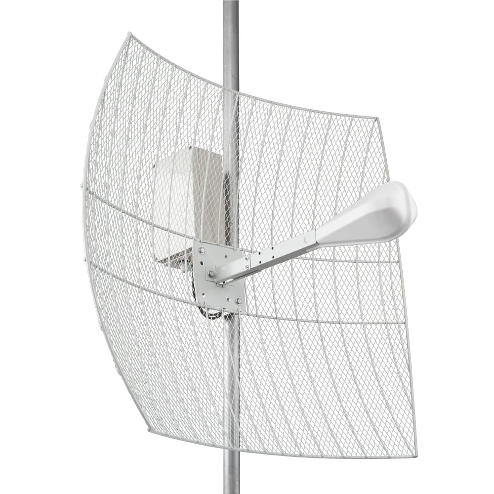
An example of modern antennas with reflectors
Another type of reflector is waveguide. A waveguide is a guiding channel with specially selected parameters in which a wave can propagate, reflecting from its walls in one direction. The first design for transmitting waves was proposed by physicist Joseph John Thomson in 1893, and a year later Oliver Lodge experimentally tested this principle. Waveguides can be acoustic (for transmitting sound waves) and electromagnetic, we are interested in the latter.
Waveguide horn antennas, in turn, are antennas using the same method for focusing or radiating from the open end of the waveguide, are essentially the same waveguide, only expanding towards the end, since the parallel waveguide itself is an inefficient emitter. By expanding the waveguide in the form of a bell, it is possible to significantly improve its characteristics, thereby achieving amplification and directivity of radiation. The shape of the horn determines what type of antenna will belong to, for example: pyramidal, conical, corrugated. The latter, by the way, have a wider bandwidth.
They are used both independently, usually as measuring, and as reflecting irradiators of other antennas. There are also antennas that structurally combine a horn and a parabolic reflector, in which case the antenna is called a horn-parabolic.
An example of a modern horn antenna
Uda — Yagi Antenna
Another, more effective type of directional antennas is the "wave channel" antenna, invented in 1926 by the Japanese Shintaro Uda, together with his colleague Hidetsugu Yagi, which later became associated with the names of researchers in Western countries.
Hidetsugu Yagi (1886 — 1976) and Shintaro Uda (1896 — 1976)
A wave channel antenna (Yaga or Uda — Yagi antenna) is a system of several vibrators having a length close to half the length of the received wave and located perpendicular to the line along which the radiation passes. Among the vibrators, the first one is active, the rest are passive (directors), their number may be different, a reflector is located on the opposite side from the directors. All elements may have a slightly different appearance, but always have a similar structure of construction, which is divided only into 2 types homogeneous and heterogeneous.
In a homogeneous structure, the distance between all directors is the same, in an inhomogeneous one, the distance may have a different pattern, where the average distance at the end of the antenna farthest from the reflector is greater, which makes it possible to achieve to some extent greater gain, but requires separate calculations when placing directors.
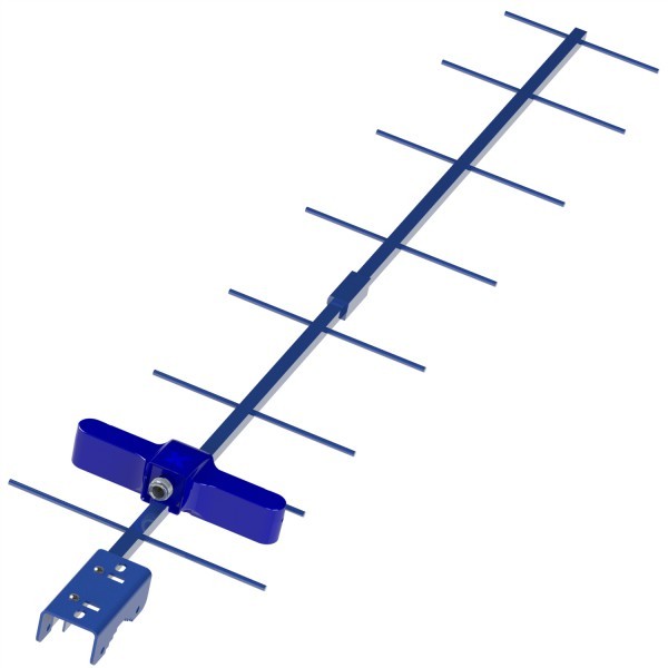
An example of a modern antenna is a wave channel
Due to their compactness, good directivity and high gain, they are extremely widespread and very often used, for example, as television antennas. They are used in meter and decimeter ranges, as well as a little less often at higher frequencies.
Theoretically, such an antenna can work without directors, but the degree of antenna gain and its radiation pattern depend on them, in other words, the radiation of the antenna is the sum of all the vibrators that make up it.
Antenna radiation pattern is a graphical representation of the distribution of the radiated antenna power at the same distance from it in different directions in one of the planes. It can also be called an image of the electromagnetic field of the antenna, clearly showing its blind spots.
Example of a directional diagram
Antenna masts
Since the signal strength depends on the height to which the antenna is raised, in order to set it to a higher height, thereby bypassing artificial and natural obstacles, improving the quality of work on the air, special support structures are used, referred to as masts. Due to the structural features, they are usually made of aluminum, if the antenna has a low weight, or steel, respectively, the greater the weight, the more logical it is to use steel masts. They are conditionally divided into portable and non-portable. How they differ should be clear from the name:
Portable ones include various folding or telescopic masts that can be temporarily installed at a certain location in a short time and also folded and moved.
Example of a portable telescopic mast
Accordingly, larger and more massive masts installed for a long period of time, not intended for frequent transfers, are non-portable. A clear example for the vast majority will be cellular communication masts.
An example of a non-portable mast structure with antennas installed on it